|
DCC System Diagram • DCC Basics •
How Does the Decoder Get
Power? • Speed Control |
Digital Command Control consists of several
parts: throttle, command station, booster, decoder, and a power
supply to run it all. An optional throttle network can be added
to have multiple walk-around throttles.
|
| DCC System Diagram |
|
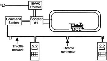
Briefly (referring to the illustration):
- You use a throttle to tell the system
what you want a train to do.
- The throttle sends the information to the
command station.
- The command station makes a digital
packet out of the information and sends it to the booster.
- The booster adds power to the digital
packet and sends it out through the rail.
- The decoders in all locomotives (even
those that are not running) read all digital packets, and
decipher them to get the address contained in the data
packet. If the packet address matches the decoder address,
the decoder uses the rest of the packet information. If the
address does not match, the decoder continues doing whatever
it was doing - whether it was running forward, backward,
with or without lights, or nothing at all
Some systems combine some of these components
into one unit. For example, Chief combines the command station
and booster. Regardless, all of these components must be
present, in one form or another, to make up the system.
NOTE: The information here is not meant to
be complete and totally technically
accurate. Since most readers will be
non-technical individuals, efforts have been
made to describe everything in general terms
that non-technical persons can understand.
If you need exacting technical information
for research and development, contact the
NMRA's
DCC working group for current
technical information.
|
BACK TO TOP
|
DCC Basics |
Before we go any further, there are three things that need to be
made clear, so you don't have a wrong pre-conception going in.
- The power on the track is AC, not DC.
- There is full power on the track at all times while the
system is turned on. Voltage is not varied to control loco
speed.
- The polarity of the electricity on the rail does NOT
control loco direction.
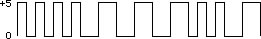 First,
the DCC power and signal on the rails is square wave AC. Think
of a normal DC computer signal square wave, as illustrated in
the diagram at right, and double it - as explained below. First,
the DCC power and signal on the rails is square wave AC. Think
of a normal DC computer signal square wave, as illustrated in
the diagram at right, and double it - as explained below.
Computer signals like this are usually measured in milliamps,
with a voltage swing from zero to 5V DC. This provides a good
signal circuit, but could hardly power a train. So, the booster
takes this signal, and amplifies it - voltage and amperage. What
you wind up with is a digital signal with enough voltage and
power to run trains.
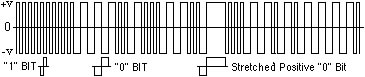 Now
for the AC part of the system. With DC power on the rail, a non-decodered
loco would simply take off at full speed. So, the same exact
signal that rises above zero is mirror-imaged to the negative
side, making a square wave signal that swings from negative to
positive - square wave AC - as illustrated in the diagram. Now
for the AC part of the system. With DC power on the rail, a non-decodered
loco would simply take off at full speed. So, the same exact
signal that rises above zero is mirror-imaged to the negative
side, making a square wave signal that swings from negative to
positive - square wave AC - as illustrated in the diagram.
The actual voltage is dependent upon the booster you're
using, and at which scale you have it set to operate.
Regardless, a short duration pulse represents a one (1), and a
long pulse represents a zero (0). A group of eight pulses
represents one byte of an information packet.
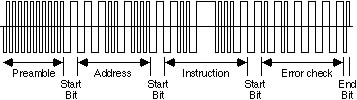 As
illustrated in the diagram here, a basic packet contains a
preamble of "1" bits, a "0" start bit, an address/data byte, a
"0" start bit, an instruction byte, a "0" start bit, an error
detection byte, and a "1" end bit - which leads into the
preamble of "1" bits for the next packet. As
illustrated in the diagram here, a basic packet contains a
preamble of "1" bits, a "0" start bit, an address/data byte, a
"0" start bit, an instruction byte, a "0" start bit, an error
detection byte, and a "1" end bit - which leads into the
preamble of "1" bits for the next packet.
As long as the duration of the negative (-) pulse matches the
duration of each positive (+) pulse, a non-decodered loco will
not move. It gets an instant of positive power trying to make
the loco go forward, then gets an instant of negative power
trying to make it go backwards. The result is a loco that sits
there buzzing. (Note: a
drop of Aero-Car Technology's
Conducta Lube on the commutator can reduce this noise).
"Zero stretching" is implemented to make the non-decodered
loco go. That is, the zero (0) pulses are stretched longer on
one side than the other. To make the loco go forward, the zeros
on the positive side are stretched. This provides more positive
power than negative. The loco still gets short pulses of
negative power, but the longer positive pulses overpower the
negative to make the loco go forward. Obviously, to make the
loco go backwards, the negative zeros are stretched. As you've
probably experienced, the faster the analog loco goes, the less
it buzzes - because the longer periods of positive power reduces
the number of AC pulses per second.
While this analog loco is running, all DCC locos continue to
run as if nothing else is happening to the signal. That's
because the decoders are designed to recognize short pulses as
ones (1), and long pulses, no matter how long, as zeros (0).
Stretched zeros are still read as zeros by decoders.
If you want to install meters to monitor track power, you
have to use AC volt and amp meters. However, even though AC
meters work, they won't be exactly accurate - because the
typical AC meter is not designed for square wave. Even so, it
will be accurate enough for general layout operation purposes.
As for how decoders use square wave AC to control and power
DCC locos, there are two parts to a decoder that use this
power/signal: the control part, and the power part.
Turning track power on also turns the decoder on. Even if the
loco has never been addressed, the controlling part of the
decoder starts reading the digital packets - all of them. Each
packet is "decoded" to get the address. If that address matches,
it acts upon the commands in the packet. If the address doesn't
match, it continues doing what the last packet for that loco
said to do. That is, if the decoder has never been addressed, it
continues doing nothing. But if the loco is running, or has a
light or other function turned on, it continues passing power to
the appropriate wires.
BACK TO TOP
|
| How Does the Decoder Get Power? |
As for the power portion of the decoder, the first thing that
has to be done is convert the AC power to DC. With AC, the
current flows in one direction (phase A, below) for one pulse,
then the other direction (phase B. below that) for one pulse,
and so on, alternating back and forth - hence, alternating
current. But, the decoder needs DC (direct current) to work.
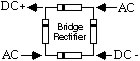 Converting
AC to DC is done with a device called a bridge rectifier, or
with four diodes configured to make a bridge rectifier (a diode
is a device that lets electricity flow in only one direction).
So, when four diodes are configured as illustrated, the rail's
AC power is converted to DC. Converting
AC to DC is done with a device called a bridge rectifier, or
with four diodes configured to make a bridge rectifier (a diode
is a device that lets electricity flow in only one direction).
So, when four diodes are configured as illustrated, the rail's
AC power is converted to DC. |
|
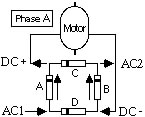
When AC flows into the AC1 connection (Phase
A, at left), diode D blocks it in that direction, but Diode A
allows it to go in that direction. Since Diode C blocks it in
that direction, it has to go out DC+. It continues through the
device being powered, back into to DC - through diode B and out
the AC2 connection. |
|
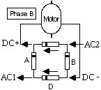
On the next cycle, Phase B, power flows into
the AC2 connection through diode C, out DC+ through the device,
then back in DC-, through diode D to go out the AC1 connection. |
|
Since this alternating transition happens so
fast, it effectively provides a constant flow of DC (direct
current) power. This explains how AC is converted to DC, but
doesn't explain how it can operate a motor in both directions.
|
|
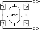 The
motor is driven by power transistors. Transistors also allow
power to go only in one direction. Consider this illustration:
to make the loco go forward, transistors T1 and T4 are activated
by the controlling circuitry of the decoder. T1 allows positive
current to enter the positive terminal of the motor, while T4
connects the negative terminal of the motor to the negative
terminal of the bridge rectifier. To make the motor go in
reverse, transistors T2 and T3 are activated. The
motor is driven by power transistors. Transistors also allow
power to go only in one direction. Consider this illustration:
to make the loco go forward, transistors T1 and T4 are activated
by the controlling circuitry of the decoder. T1 allows positive
current to enter the positive terminal of the motor, while T4
connects the negative terminal of the motor to the negative
terminal of the bridge rectifier. To make the motor go in
reverse, transistors T2 and T3 are activated. |
|
BACK TO TOP
|
| Speed
Control |
Since there is full voltage on the rails at all times, there is
also full voltage available at the power transistors at all
times. If the transistors are turned on to pass available
voltage, the loco will take off at full speed. Unlike a water
faucet, transistors are designed to pass full voltage, or no
voltage. With a water faucet, if you want to pass 10 gallons per
hour, you can simply turn the volume down and it will dribble 10
gallons per hour. But what if you have a valve that is either on
or off. How would you get an even flow of water that would
produce 10 gallons per hour? Simple, turn it on for one second,
then off for a few. So, these power transistors are turned on
(triggered) for a brief period of time, then turned off for a
time depending on how fast the loco is to go.The difference
is that the transistors are turned on and off hundreds of times
per second - so fast that the motor can't respond
instantaneously to each pulse. The motor has so much mass to it
(including flywheels) that a single pulse can't budge it. But, a
whole lot of pulses can make it go. This is part of why
locomotives run so much better on DCC than with DC analog.
A motor takes more voltage to get it started than it does to
keep it going. For example, you've probably experienced
increasing analog voltage to the tracks to a point where the
loco lurches to a start, but can then reduce voltage to keep it
going at a slower rate than it started. Well, DCC hits the motor
with pulses of full voltage, so the full-voltage pulse can bump
the motor to start, but doesn't provide the power long enough to
make it lurch.
Consider this: to make a loco run at 30% throttle with DC
analog, you will be providing 30% of the available voltage all
the time. But with DCC, you provide full voltage 30% of the
time.
BACK TO TOP |
Originally appeared as an
article on
Loy's Toys Website
Article content copyrighted © 2007 Loy Spurlock, all rights
reserved
Reproduced here with the permission of Loy Spurlock |